In vivo confocal microscopy, an inner vision of the cornea – a major review
Abstract
The demands of modern ophthalmology have evolved from descriptive findings from the slit lamp to in vivo assessment of cellular level changes. Nowadays, the latter can be provided by in vivo confocal microscopy. This article gives an overview of confocal principles using tandem scanning, scanning slit and laser scanning techniques used in ophthalmology. The main part of the paper describes the clinical applications emphasizing the anatomy of the normal and pathological cornea, and illustrates side-effects of topical medication, contact lens wear, cross-linking and refractive surgery. Finally, a summary about experimental applications, including animal studies, surface characterization and volume rendering as well as future developments, is given.
Introduction
Early and reliable diagnoses in ophthalmology usually depend on the recognition of minute changes in normal structures. The functional consequences of such pathological alterations may be the only aspect of concern to the patient; however, ophthalmologists look for reproducible morphologic criteria that are essential in defining health and disease. Clinicopathological correlations including ‘biomicroscopy’ and ‘biocytology’ have been very rewarding approaches to improving definitions of the disease phenotype.
Until recently, despite published images of tissue microstructure, in vivo confocal microscopy (CM) remained largely a tool for research laboratories with an interest in the clinical applications of prototype instruments. Currently, however, there are instruments available on the market that have quite clearly made the step from ‘bench to bedside’.
Principles of confocal microscopy
Confocal principles
The most common method of tissue analysis is the histological examination of excised tissue. The non-invasive alternative is in vivo cell imaging, using light reflected from within the tissue. Changes in the index of refraction or the use of fluorescent agents provide information to aid recognition of inter- and intracellular details and have the potential to yield sufficient information to detect tissue alterations.
A confocal microscope (CM) is an imaging instrument in which a specimen, such as the cornea, is illuminated with a focused light spot. A light beam passes through a light source aperture and then is focused by an objective lens into a small focal volume within a specimen. A mixture of emitted as well as reflected light from the illuminated spot is then recollected by the objective lens. A beam splitter separates the light mixture and reflecting the light into the detection apparatus. After passing a pinhole, the light is detected by a photodetection device, transforming the light signal into an electrical one that is recorded. The detector aperture obstructs the light that is not coming from the focal point, resulting in sharper images than those from conventional light microscopy techniques.
Background information on the general field of CM is presented in detail in several sources.1–4
To summarize, a confocal arrangement isolates information from volume elements without the necessity of physical sectioning. Technically, the confocal arrangement can be realized in different ways.
Types of confocal microscopy
In contrast to conventional microcopy in which the image can be observed directly (all points in the specimen are imaged parallel), a CM optimizes illumination and detection for a single spot only. For two-dimensional imaging the sample must be scanned sequentially.5
Tandem scanning-based confocal microscopy
A real-time tandem scanning CM was developed by Petran and Hadravsky. The basic part of the system was contributed by Nipkow, who invented a disk in 1884 to provide real-time point illumination and point detection. The properties of the system are real-time at video rates, true colour and direct observation, in combination with a marginal image quality based on the low intensity of the reflected light.6
A step forward was the development of the one-sided Nipkow disk CM based on the work of Xiao et al.,7,8 using the set of pinholes on the same side of the Nipkow disk for illumination and detection. Although this is a simpler design, it has the disadvantage of low intensity of illumination for image formation.
A clinical version of this original microscope was produced by the Tandem Scanning Corporation (Reston, VA, USA) and later by the Advanced Scanning Corporation (New Orleans, LA, USA), but is no longer in production.
Scanning slit confocal microscopy
Scanning time can be markedly reduced by using a slit for scanning, where all points in the axis of the slit will be scanned at the same time. Background information and details about design and advantages have already been published.5
The slit height can be adjusted, which allows the user to vary the thickness of the optical section, and the slit width adjustment allows control of the amount of light that reaches the cornea. However, the use of the slit also means that this microscope is truly confocal in the axis perpendicular to the slit height and the contrast of the system is very low.
Slit scanning in vivo CMs are commercially available from different sources, including Tomey Corporation (Cambridge, MA, USA), Nidek Technologies (Gamagori, Japan) and Helmut Hund (Wetzlar, Germany).
Laser scanning confocal microscopy
The CM, invented by Minsky, is being developed as a new optical technique for clinical examination of the human eye.9–11 The next step in clinical CM is the scanning laser ophthalmoscope developed by Webb.12–14 A coherent laser is used as a high intensity light source and the laser beam is scanned by a set of galvanometer scanning mirrors providing fast scanning about the xy plane. The reflected light refocused by the microscope objective is scanned by the galvanometer scanning mirrors again, and imaged on a pinhole aperture located in front of the photomultiplier.
The Heidelberg retina tomograph (HRT) (Heidelberg Engineering, Heidelberg, Germany) is one of the well-established in vivo confocal imaging systems in ophthalmology. HRT is a device with a 670 µm diode laser designed to acquire and evaluate topographic measurements of the optic nerve head to detect glaucomatous damage.
Stave et al. (University of Rostock, Germany) modified the HRT with the use of a detachable objective system, the so-called ‘Rostock cornea module’ (RCM),15 into a high-resolution confocal laser scanning microscope (CLSM) for the visualization of the anterior segment of the eye (Fig. 1).
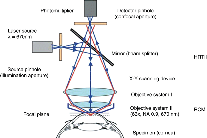
Schematic principle of the confocal arrangement implemented in the HRT-II + RCM system for in vivo confocal microscopy of the cornea. HRT, Heidelberg retina tomography; RCM, Rostock cornea module.
Because of the high-depth resolution, optical sections of only a few micrometers can be imaged and precisely measured in combination with a high contrast. Currently, state-of-the-art CM in ophthalmology using the laser scanning technique is a tool not only for corneal research, but also for evaluation of the conjunctiva, sclera, limbal region, lid, lacrimal gland and tear film as single anatomical units and as parts of eye-associated lymphatic tissue.16
Image formation
In general, a CM is a type of microscope where a specimen is illuminated with a focused spot of light, preferably a laser source. Because of the special setup of the microscope, only rays from the confocal plane will be detected. Transverse and axial resolutions are enhanced in comparison with a conventional microscope using the same wavelength and objective. In order to obtain maximal axial resolution, microscopic objectives with a large numerical aperture should be used. This enhanced axial resolution permits improved optical sectioning of the cornea and their three-dimensional (3D) reconstruction.
Image quality is not only characterized by resolution, but also by contrast. Contrast depends on illumination level, refraction index and the reflectivity of the studied tissue. Penetration depth is limited by two factors: signal-to-noise ratio and background intensity.
Clinical application
To date there are around 900 published papers dealing with in vivo CM of the cornea (source: Pubmed, April 2008). The following summarized results are in line with the known histology of the cornea and have been reported in recent publications.16–20
Normal cornea
Superficial cells (Fig. 2a) are characterized by a polygonal cell pattern, bright illuminated cytoplasm, reflecting nucleus and perinuclear dark halo. Cell size is up to 50 µm in diameter and about 5 µm thick with individual variations.21 The average density in the corneal centre and periphery is from about 624 cells/mm2.22 to 1213 cells/mm2.23
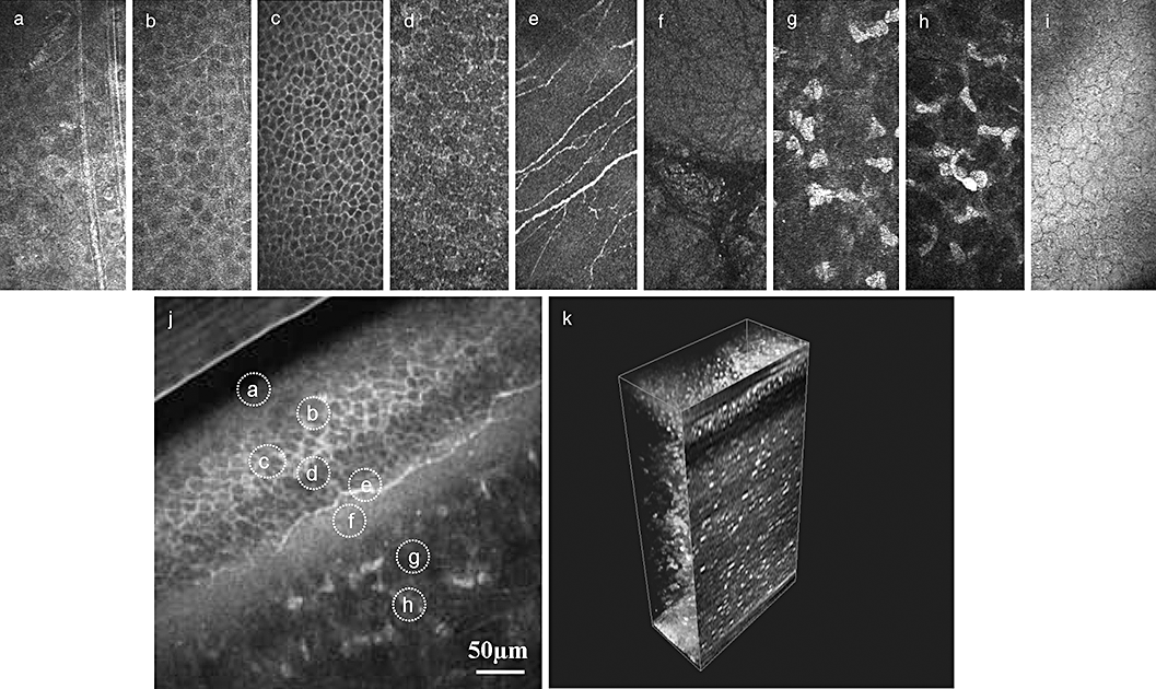
In vivo confocal images of the normal cornea. (a) Superficial cells. (b) Upper wing cells. (c) Low wing cells. (d) Basal cells. (e) Sub-basal nerve plexus. (f) Bowmane's membrane. (g) Anterior stroma. (h) Posterior stroma. (i) Endothelium. (j) Oblique section through corneal epithelium and anterior stroma – all layers are present. (k) Three-dimensional (3D) reconstruction of the whole cornea (see 3D reconstruction section).
The cells of the epithelial intermediate layer, or wing cells (Fig. 2b,c), form a regular mosaic with sharp and reflecting cellular borders. The wing cells are smaller in size (about 20 µm) but regular in form. They can also be subdivided into upper (Fig. 2b) and lower (Fig. 2c) wing cells; the latter are smaller.19 To date there are only a few studies reporting the cell count in this layer.24 The average density is 5000 cells/mm2 in the corneal centre and 5500 cells/mm2 in the periphery.24
Basal epithelial cells (Fig. 2d) have a smaller diameter (8–10 µm) and appear as a layer of cylindrical cells where nuclei cannot be remarked by a reflecting border. The average density varies from about 600023 to 900025 cells/mm2 in the corneal centre and 10 000 cells/mm2 in the periphery.24
The ratio between superficial, intermediate and basal cells (accordingly to the cell density) is approximately 1 : 5 : 10,24 whereas another two studies report ratios between the superficial cells and basal cells of 1 : 523 and 1 : 7.25 The difference in cell ratios in these studies was interpreted by the strategy to study the lowest layer of basal cells situated directly over the Bowman's membrane, where the highest cell density is expected.24 There are no published data about cell count changes caused by age in any cell layer of the epithelium.
The sub-basal nerve plexus (SNP) (Fig. 2e) is characterized by the presence of hyper-reflective fibres of 4–8 µm length,26–29 connected with anastomoses and organized in a vortex pattern in the lower nasal quadrant of the paracentral cornea. A two-dimensional reconstruction of the SNP maybe performed, allowing mapping of the central 5 mm of the cornea.30
The Bowman's layer (Fig. 4f) is an 8–10 µm thick zone consisting of randomly arranged collagen fibrils located in between the basal cells and the stroma. Moreover, in vivo CM shows polymorphic structures composed of fibrillar materials (K-structures) beneath the Bowman's layer in normal human subjects. It was presumed that these microstructures (5–15 µm in diameter) might correspond to the modified and condensed anterior stromal collagen fibers/lamellae that merge into the Bowman's layer and that these fibrillar materials may be responsible for the formation of the anterior corneal mosaic.31,32
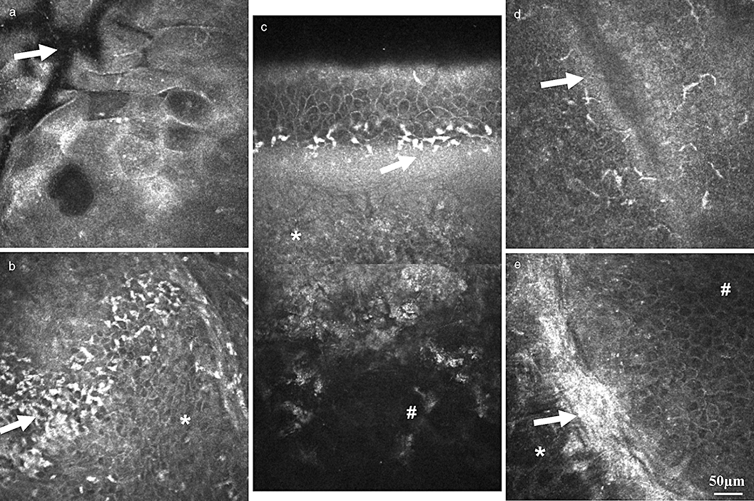
Phases of development of the corneal ulcer. (a, b) Progressive phase: oedema of epithelium and stroma: (a) swelling of superficial cells, note the border of the ulcer region (arrow); (b) oedema of wing and basal cells (*), infiltration with inflammatory cells (leucocytes and Langerhans cells – arrow). (c,d) Regressive phase: (c) reconstruction of oblique section – minimal epithelial oedema, all epithelial layers are visualized, inflammatory cells at the level of the SNP (arrow), development of scar tissue (*), intact stroma (#); (d) ulcer edge (arrow) wit inflammatory cells. (e) Healing phase, ulcer edge: intact stroma with a normal keratocyte pattern (*), scar tissue formation at the ulcer edge (arrow) and regular pattern of the regenerated wing cells (#) are presented. Depth difference between the stroma (*) and wing cells (#) is about 40 µm.
Corneal stroma (Fig. 2g,h) forms around 80–90% of the whole corneal volume. It consists of three main histological components: cellular, acellular and neurosensorial. The keratocyte nuclei are visible as egg-shaped reflecting light corpuscles, whereas the connective lamellae appear black (that is transparent) because of their optic properties. Patel et al. presented a review of 18 studies of keratocyte density in normal corneas.20 Taken together, keratocyte density is highest in the anterior stroma, clearly declines toward the central stroma, and increases again slightly in the posterior. The density of keratocytes decreases with age.33,34 The stromal nervous fibres, which are thicker than the subepithelial ones, run along the stromal tissue along a straight pathway, although it is sometimes possible to find dichotomous branches (T and Y shapes).19
Descemets membrane is a thin (6–10 µm) homogeneous layer, located in between the posterior stroma and endothelium, and is not visible with CLSM.
The endothelium (Fig. 2i) is a monolayer of cells arranged in a hexagonal pattern of honeycomb regular mosaic, where the cells are normally identical in size and shape, that is, without signs of polymegatism and pleomorphism. Sometimes it is possible to visualize the nucleus of the cells. The total number of cells is about 500 000 in a healthy subject with a normal cell density of 2500–3000 cell/mm2.19,24 The cell density decreases with age.35
Confocal laser scanning microscope enables not only en face imaging but also oblique cuts through several layers, offering a direct parallel to the traditional histological images (Fig. 2j).
Light scattering phenomenon determines the reflectivity of cells. The main factors influencing on the interaction of light beam and its transmission and absorption are, according to Bochard, cellular organelles and membranes, microvilli, microplicae and glycocylix.36,37 It was postulated that the presence of microdesmosomes in the epithelial layers could explain why the cell membranes of epithelial cells were more brightly illuminated (Fig. 2a,d) than those of the endothelial cells (Fig. 2i).
Pathological cornea
Cell types
In vivo imaging of the pathological cornea presumes that different cell types can be reliably and quickly differentiated. We summarize the differential diagnoses between various cell types in the cornea, with an emphasis on cell morphology. Staining was performed in parallel studies and has been shown elsewhere.19
Leucocytes present as hyper-reflective oval-round cell bodies, located at the level of the wing or basal sells or SNP (Fig. 3a). Histologically, this cell type is subdivided into granular leucocytes, that is, neutrophils, basophils and eosiniphils and non-granular leucocytes, that is, monocytes and lymphocytes (Table 1). CLSM does not allow the clinician to distinguish cell characteristics, such as the presence of nucleoli or granules. Nevertheless, basic clinical information, such as the typical cell morphology, diameter of the cell body and location of the cell, all aids the clinician in the correct interpretation of the confocal data.38
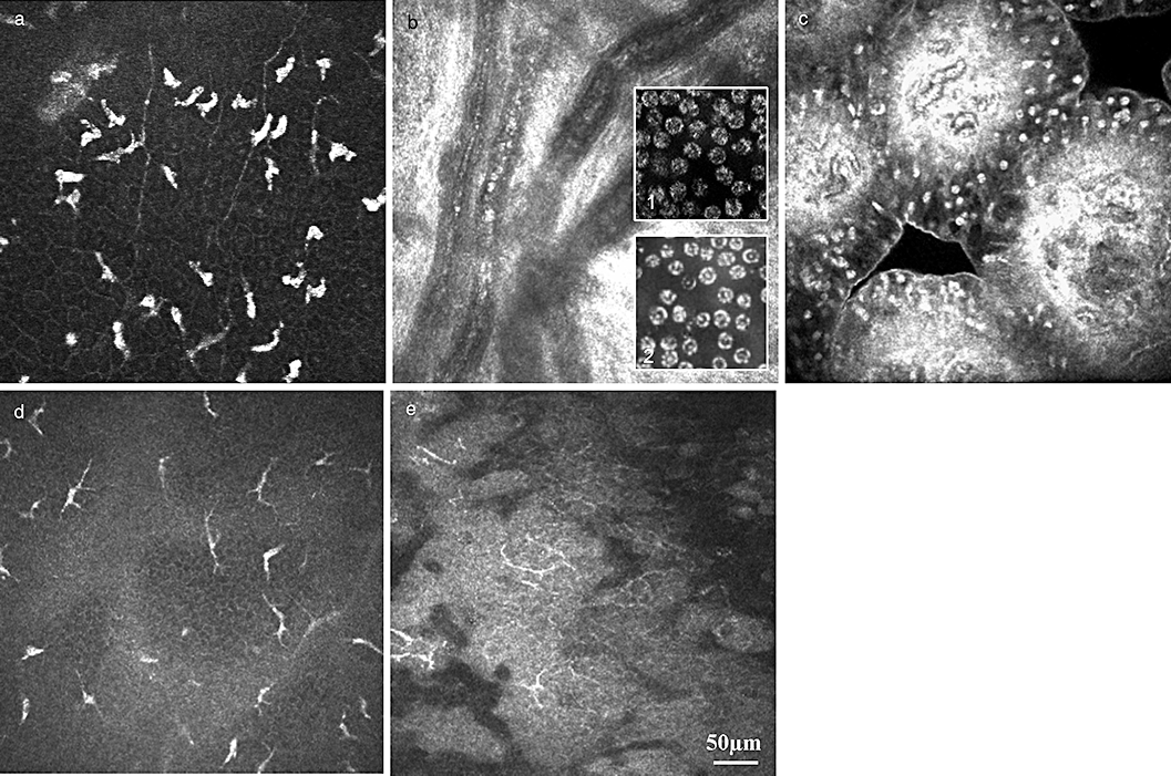
Representative confocal images of cell types. (a) Leucocytes – hyper-reflective greasy cells, located at the level of the basal cells and sub-basal nerve plexus. (b) Blood corpuscular elements in the vascularized cornea: cell elements are presented as hyper-reflective cell bodies. Parallel confocal microscopy of blood smear: (1) leucocytes – the subdifferentiation is not possible; (2) erythrocytes with the typical biconcave surface and homogenous cytoplasm. (c) Lymphocytes – hyper-reflective cell bodies, located in the follicles of the tarsal conjunctiva. (d,e) Dendritic cells – typical spider-like structure of dendritic cells at the level of basal cells or the SNP of the corneal epithelium (d) or in the conjunctiva (e).
| Leucocyte type (cell count in %) | Size (µm) | Confocal microscopy |
|---|---|---|
| Granular leucocytes | <10 | The differentiation of granylocytes is based on the tiny granules and number of nuclear lobes, which are specific for each cell type. These ultrastructures are not visible with CLSM. All granulocytes are motile. |
| Neutrophils (50–70%) | ||
| Basophils (5%) | ||
| Eosiniphils (1%) | ||
| Non-granular leucocytes | ||
| Monocytes (3–9%) | Up to 20 | The largest granulocytes. This cell type is a precursor of macrophages, and contains kidney bean-shaped nuclei and granules not visible with CLSM. These cells are typically seen in the blood vessels of the cornea or conjunctiva.Macrophages are smaller (12–15 µm) and are present at the ulcer or infiltrate area. |
| Lymphocytes (25–35%) | Up to 15 | The second most numerous leucocyte. Hyper-reflective cells which can be easily found in the palpebral and tarsal conjunctiva. |
- CLSM, confocal laser scanning microscope.
Erythrocytes are non-nucleated, biconcave discs averaging 7 µm in diameter (Fig. 3b). The presence of hyper-reflective reflex in the middle of the disk is a typical sign and underlines the biconcave cell morphology.19
Another cell population are dendritic cells or Langerhans cells (LCs). LCs are a critical factor in antigen presentation in the cornea and conjunctiva.16,39–41 LC might be an important regulator of immune reactions and modulate between immune defence und immune tolerance. LCs present as either large cells with long processes or smaller cells lacking cell dendrites, supposedly indicating mature and immature phenotypes, respectively (Fig. 3d,e). The LCs were identified and the distribution measured immunohistochemically. Quantitative evidence of LC in the cornea and conjunctiva could be of clinical relevance in the evaluation of wound healing, graft versus host disease, allergic and toxic drug side-effects, etc.
In healthy volunteers, in vivo CM revealed LCs in 1/3 of all volunteers, with LCs presenting both in the centre and the periphery of the cornea with densities of 34 ± 3 and 98 ± 8 cells/mm2, respectively.40
Corneal disease
Corneal infiltrate
Corneal infiltrate is characterized by infiltration with inflammatory cells at the level of the lower wing and basal cells without any other morphological changes of the cornea. The leucocytes present as hyper-reflective oval cell bodies about 12–15 µm in diameter. The LCs present as spider-like cells that create a net with the other LCs.38
Corneal ulcer
Corneal ulcers can be observed occasionally as a result of infections, contact lens wear or in dry eyes. CM represents a new tool for the differential diagnoses of pathological processes and provides the possibility for dynamic healing control. An advanced process such as the corneal ulcer is characterized by not only tissue defects but also by oedematous structures of the entire cornea resulting in corneal thickness increase, increased cell density of leucocytes and LCs.38
The development of the ulcer can be divided into three stages: progressive, regressive and the healing phase. The progressive phase is characterized by tissue defects (Fig. 4a,b). The CLSM enables differentiation between the intact and pathologically changed structures of the epithelium and stroma.19,38 Epithelial oedema is typically presented with elongated and increased superficial cells. The stroma shows an inhomogeneous distribution of keratocytes. Jester42 suggested that increased expression of transketolase, as well as aldehyde dehydrogenase class 1, is typical only for a normal transparent cornea (Fig. 4c) and has demonstrated that increased backscattering is typical only to opaque corneal areas where the concentration of these proteins is reduced. In advanced cases both epithelial as well as corneal thicknesses are increased. Epithelial thickness is determined as the distance between the superficial cells and the SNP. The infiltration of the epithelium as well as the conjunctiva with inflammatory cells (leucocytes and LCs) is also typical. LCs presented as either large cells bearing long processes or smaller cells lacking cell dendrites, most supposedly indicating mature and immature phenotypes, respectively.16
The regressive phase (Fig. 4c,d) shows the decrease of the inflammatory cells and the tissue defects start to heal. The proliferation of the basal cells, as well as regeneration of the fibrotic tissue at the Bowman's membrane defect area, is typical. Finally, the scar tissue formation can be identified (Fig. 4e). One of the main advantages of the CLSM is the possibility of the in vivo follow up by corneal pathology.
Differential diagnosis
Confocal laser scanning microscope enables the differential diagnosis of different pathogens and, so far, the differentiation between bacterial, fungal or protozoan agents (Fig. 5).
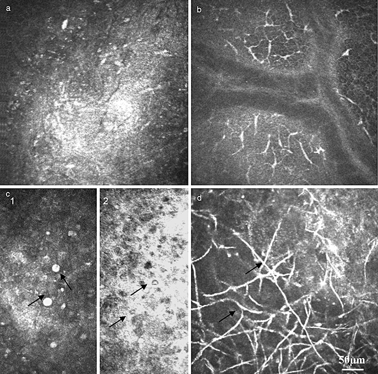
Confocal microscopy and differential diagnosis of the ulcer. (a) The ulcer bottom is presented with hyper-reflective surface without any additional information. (b) Bacterial ulcer: massive infiltration with inflammatory cells (leucocytes and dendritic cells). (c) Protozoan ulcer: typical hyper-reflective Acanthamoeba cysts with up to 20 µm diameter located in the epithelium (arrow) (c1) as well double-walled structure (c2) located in the stroma. (d) Fusarium solani keratitis: hyper-reflective linear hyphae in the stroma (arrow) (courtesy of A. Labbe/Paris).
Bacterial ulcers show as typical hyper-reflective defects without the structure of the ulcer bottom being recognizable (Fig. 5a). The adjacent epithelium is oedematous. The basal cell level as well as the SNP is infiltrated with leucocytes and LCs (Fig. 5b). The pathogen art differentiation is not possible.
Viral keratitis (herpes keratitis, epidemic keratoconjunctivitis) can be easily and accurately diagnosed by the presence of wire netting of the SNP fibres and dendritic cells.16,43 In the acute phase of the pathological process, LCs are located at the level of the lower intermediate cells, basal cells and nerve plexus. The decrease in dendritic cell density is a clear, indirect sign of recovery, a sign that can be used in clinical practice.
Quick and reliable identification of Acanthamoeba is one of the most acknowledged applications of CM in clinical practice.16,19,20,44–46 The typical structure of Acanthamoeba cysts and trophozoites allows rapid diagnosis and effective treatment. The cyst forms are presented as highly reflective, round-shaped particles 10–20 µm in diameter within the corneal epithelium and stroma (Fig. 5C). It is possible to find cysts as single, round-shaped structures, (Fig. 5C-1) or double-walled structures (Fig. 5C-2) as well as conglomerates.
Mathers et al.46 compared the results of CLSM with the polymerase chain reaction, and in 77% the diagnosis was correct. So far the combination of clinical experience and expert knowledge allows immediate diagnostic and appropriate therapy.
Diagnosis of fungal keratitis is the other key advantage of CM (Fig. 5d). Nevertheless, corneal scrapings for smears and cultures are still the primary diagnostic tool. CLSM is able to reveal numerous hyper-reflective elements resembling Fusarium, Aspergillus hyphae or Candida pseudofilaments in the anterior stroma even in the early phase of the disease.19,38,47,48 These findings are often associated with the presence of inflammatory cells (leucocytes as well as LCs). Brasnu et al.48 compared in vivo CM findings with the results of corneal smears and culture evaluation, and proved that using CLSM the clinician is able to determine the fungal agents. Moreover, it offers the in vivo possibility of fungal differentiation. Fusarium solani typically displays the presence of multiple highly reflective linear formations (hyphae) up to 300 µm in length and 5 µm in width, with branches at 90° angles in the anterior stroma. In contrast to hyphae, the Candida pseudiphilaments are characterized by numerous hyper-reflective particles from 10 to 40 µm in length and from 5 to 10 µm in width located in the anterior stroma. When the fact that invasive methods, such as the culture of corneal scrapings and biopsy specimens or PCR, have different grades of sensitivity and the fact that only about 25% of results are positive to the second week are taken into consideration, CLSM can be considered a rapid and reliable clinical diagnostic tool.
One of the main questions is the sensitivity and specificity of the CM. Kanavi et al.49 compared the results of corneal and/or contact lens case smear and culture in the diagnosis of infectious keratitis with the CM findings. Corneal and/or contact lens case smear and culture were positive in over 50% of eyes, including 40 cases of bacterial, 16 cases of fungal and 15 cases of acanthamoeba infection. CM revealed the pathogens in about 40% (50 eyes); 27 eyes with hyphae-like structures and 23 cyst and/or trophozoite-like structures. The sensitivity and specificity of confocal scans were 100% and 84% for the diagnosis of acanthamoeba keratitis versus 94% and 78% for fungal keratitis, respectively.
So far, in vivo CLSM is a rapid and reliable clinical tool for the diagnosis of acanthamoeba and fungal keratitis with high sensitivity and specificity compared with traditional smear and culture. Nevertheless, clinical situation and the experience of the ophthalmologist also play a decisive role in the treatment of the patient.
Side-effects of topical medication
Various side-effects of topical medication can be visualized with in vivo CM and utilized in research and practice.
Influence of preservatives on the ocular surface
It is well known that preservatives can induce dry eye conditions due not only to changes in tear film production and quality but also to damage and inflammation of the ocular surface. A number of studies have shown preservatives to be allergic and/or toxic.50,51
It has been also shown that BAC is the most toxic preservative used in ophthalmic preparations52 because of its high penetrating capacity. The toxic effects depend on the dose and duration of exposure. Thus, a moderate 0.01% BAC solution induces marked epithelial changes: complete loss of microvilli, degenerative membrane changes and desquamation of the two superficial epithelial cell layers after three hours’ exposure.53 CM has revealed desquamation of the surface layer within 30 min of exposure to 0.005% BAC.54 Damage and inflammation of the ocular surface lead to the dry eye symptomatic-like irregularity of the corneal surface, increase of inflammatory cells and disturbance of the tear film.16,19
Topical side-effects of mitomycin C on cornea after pterygium surgery
The other example of toxic influence of local therapy is mitomycin C (MMC), an anthracycline derived from Streptomyces caespitosus, which has both antineoplastic and antiproliferative properties. Its application inhibits fibroblast proliferation during the postoperative phase without damaging mucosal and epithelial growth. However, use of MMC is associated with serious complications, especially at higher cumulative doses
Our group showed55 that after application of MMC 0.02%, complete epithelialization of the operated zone was found 2 weeks post surgery. In vivo CM revealed signs of superficial punctate keratitis for 2 weeks in the central cornea only after application of MMC (Fig. 6a). The presence of epithelial and stromal oedema in this group was noted for up to 2 weeks in the central cornea and for up to 4 weeks in the operated zone. In the control group, complete epithelialization was found after 1 week, there were no signs of oedema after 1 week in the central cornea and after 2 weeks in the operated zone. Leucocyte infiltration and increased LC density were noted in both groups in the operated and central zones. Analysis of the conjunctiva revealed a decrease in goblet cell density following cytostatic application. So far, local application of MMC delays corneal epithelialization, and prolongs postoperative epithelial and stromal oedema in both the centre and periphery (Fig. 6). Moreover, signs of punctate keratitis were noted 2 weeks after surgery in the central intact cornea. Nevertheless, in vivo CM shows that these changes are reversible 4 weeks after application of MMC 0.02%.
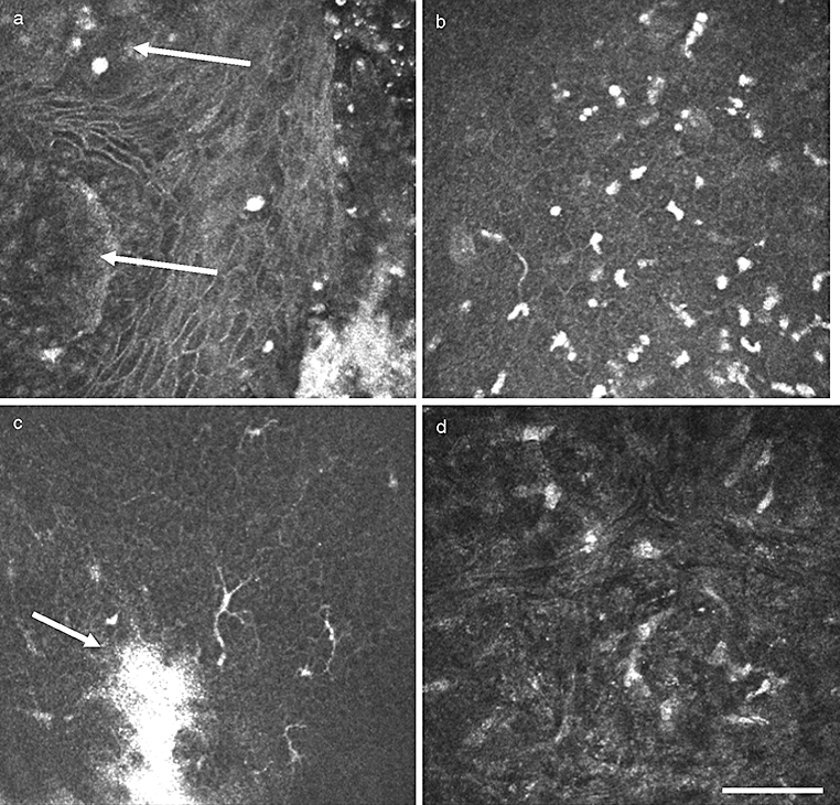
Representative confocal images of the toxical influence of mitomycin C on the ocular surface. (a) Operated zone: edematous intermediate cells of the corneal epithelium with epithelial defects as acellular zones (arrows) at the level of the intermediate cells. (b) Massive infiltration of the inflammatory cells (most supposedly, leucocytes and dendritic cells) at the level of the wing cells in the central cornea. (c) Hyper-reflective areas at the level of the superficial, wing and basal cells with up to 200 µm in diameter considered as superficial punctate keratitis (arrow) at the level of the wing cells in the central cornea, dendritic cells. (d) Oedema of the anterior stroma: irregular pattern of keratocytes with increased back scattering.
Contact lens wear
Distinct changes in corneal morphology, pachymetry and structure in contact lens wearers can be demonstrated by in vivo CLSM.
Epithelial changes, such as compression of the superficial cells, formation of mucin balls over the complete epithelial thickness by hydrogel contact lenses with subsequent activation of keratocytes, have already been discussed elsewhere.56 Increase of LC density as a reaction of the corneal surface (and the whole eye associated lymphatic tissue system as well) allows speculation about the changes in the immune status of the cornea. Both mature and immature forms of LC are typically present at the level of wing and basal cells.41 Moreover, an increased number of rolling leucocytes in the limbal vessels has been described by Efron.56 Continuous mechanical stimulation of the ocular surface, applanation of different contact lens storage solutions, different grades of oxygen transmissibility all change the immune status of the cornea and increase the risk of infection.
It has been reported that over 50% of contact lens wearers have LCs in their central and peripheral corneas.41 When compared with healthy volunteers, the LC densities of contact lens wearers are significantly higher in both the central (78 ± 25 cells/mm2) and the peripheral cornea (210 ± 24 cells/mm2), whereas the gradient of LC density from peripheral to central cornea was found to be almost identical in both groups. In the central cornea, LC density significantly decreased with the duration of contact lens wear.16,41
Typical changes observed in the stroma are the presence of hyper-reflective panstromal microdot deposits.16 An increased number of microdot opacities compared with the non-lens wearing eye is apparent,6,57 and has been associated with the duration of contact lens wear. These microdots are thought to be granules of lipofuscin-like material.
All cell layers (superficial, intermediate and basal cells) are present and characterized by bright cell borders and uniformly dark cytoplasm. The cell count increases with layer depth because of a decrease in cell diameter. Ladage has postulated that contact lens wear stimulates the proliferation of basal cells, slows desquamation of superficial cells and inhibits the turnover of the corneal epithelium.58,59
Eckard et al. quantified the changes in the epithelium, which can be summarized as follows: cell bodies of superficial cells are generally smaller (30 µm in contact lens wearers and up to 50 µm in the normal cornea).19 A significant increase in superficial cell density existed both centrally and peripherally. Structures of intermediate and basal cells were found to be identical to the normal probands. The cell counts of both cell types were significantly reduced only in the periphery. Corneal thickness in the corneal periphery decreased in proportion to the duration of contact lens wear. Age-related changes in cell count or epithelial thickness were not found. Stromal thickness was reduced in elderly contact lens wearers.
Signs of polymegethism, pleomorphism and endothelial precipitates are the most common findings in the corneas of contact lens wearers.16,19,57
Corneal cross-linking
Collagen cross-linking with riboflavin and UVA light is considered to prevent or delay the progression of keratoconus.60,61 CLSM enables visualization of the photopolymerization effect,62,63 as well as possible complications of the procedure.
Rarefaction of keratocytes in the anterior and intermediate stroma, associated with the stromal oedema, was observed immediately after treatment.62 Our data show the appearance of the honeycombed anterior corneal stroma, but without the typical hyper-reflective keratocyte nuclei, just after cross-linking (Fig. 7). These structures are thought to represent activated keratocytes characterizing with the highly reflective cell nuclei with their cytoplasm and cytoplasmic processes. Complete repopulation of the keratocytes was found 6 months after the cross-linking. No endothelial damage (change of the endothelial cell count or morphology) was observed at any time.64
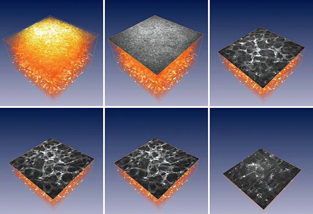
In vivo confocal laser scanning microscope of the cornea after cross-linking treatment (UVA + riboflavin) of progressive keratoconus (volume rendering and en face sections in different depths).
Corneal refractive surgery
Refractive surgery is one of the most dynamic developing facet of modern ophthalmic surgery. It is of great importance to obtain the most reliable information about healing processes. Cellular changes are often not visible using the normal slit-lamp technique, which is why the CLSM offers a useful opportunity.19,20,65 Wound healing after photorefractive keratectomy (PRK) as well as laser in situ keratomileusis (LASIK) could be reliably controlled, and haze development, interface zone, activated keratocytes, reinnervation and possible complications, such as epithelial ingrowths or fibrosis, could be easily identified. Another useful measureable parameter is the real flap depth (Fig. 8).

Representative confocal microscopic images after laser in situ keratomileusis 12 month postoperatively. The central flap in a depth of 160–170 µm with high reflective particles in a depth field of 20 µm.
It has been shown that real flap depth is thinner than the planned one, and that there are no changes in flap thickness over time.66,67 However, some studies have shown an increase in flap thickness.68 The depth of the flap can be easily quantified as the distance between the superficial cell layer and the interface zone. The latter is characterized by the presence of multiple hyper-reflective spots in the interface zone, as well as hyper-reflective (activated69) keratocytes.19 These signs of the interface zone decrease over time, but still present many years after LASIK66,70 and act as a landmark for CM. Until now, it has not been possible to determine the nature of this debris, which could consist of both organic and inorganic material (the residual materials of microkeratomy, secretion of meibomian gland, cellular debris).65 It has been speculated that haze originates from these activated keratocytes rather than from the extracellular matrix deposition. Moreover, a significant decrease in keratocyte density (the so-called acellular zones both sides of the interface) has been reported. Kaufman et al.65 described a decline in the keratocyte cell count within the flap zone during the 3-year follow-up period. These data could help to evaluate long-term corneal stability, refractive stability and cellular integrity after LASIK.
Reinnervation of the cornea is a cornerstone question in refractive surgery. CLSM allows easy detection of the SNP, and it is possible to track separate nerve fibres from the limbal area over the cut zone to the central cornea. The literature review shows contradictory data reporting that re-innervation in the central cornea starts somewhere between the first and sixth month. The SNP has completely recovered 2 years after PRK71 as well as after LASIK (our data), but even months after total restoration of corneal sensation the typical normal architecture of the corneal nerve anatomy could not be found. Our studies also show the possibility of complete regeneration of the whirlpool pattern after LASIK.
The other possible application of CLSM is the evaluation of haze. Haze can be described as the degree of backscattering of light by the cornea. Physiologically, it is explained by a keratocyte repopulation response with a higher density and reflectivity of migratory fibroblasts and myofibroblast transformation after repopulation.72,73
Imaging of the filtering bleb
One advantage of the recent advancement of CM is the ability to image the filtering bleb.74–77 It allows the analysis of bleb microstructures that are invisible under a slit lamp, as well as estimation of the bleb function. Thus, the epithelial microcysts, total stromal cyst area, absence of encapsulated stromal cysts and minimal vascularisation, as well as the absence of tortuous conjunctival vessels, are the signs of a good bleb function.76 The sub-epithelial connective tissue is widely spaced in functioning blebs, whereas the tissue is dense in non-functioning blebs.74,75 Moreover, Guthoff et al. classified the stromal structure into four patterns (trabecular, reticular, corrugated, compacted). The trabecular structure occurs only in functioning blebs, particularly in the early postoperative period. In contrast, corrugated, reticular or compact stromal patterns in early blebs tend to indicate a less favourable functional status.77
Experimental application
Animal studies
Few in vivo microscopy data are available on the normal corneal anatomy of rabbits,78 rats79,80 and mice.81,82 An interspecies comparison is given by Labbe et al. comparing the anatomy of standard laboratory animals (rabbits, rats, mouse).83In vivo CM has been used in animal studies to assess the corneal surface after the application of topical drugs or preservatives,54,84 and to analyse corneal response after refractive surgery85,86 or alterations after contact lens wear.87,88
Surface characterizazion and volume rendering
In recent years knowledge about the ocular surface has been significantly enriched through the use of CM.16,89 Three-dimensional analysis of data permits evaluation not only of pathological findings but also of regenerative tissue processes at the cellular level.19,20,90
In principle, 3D reconstruction using the tandem scanning principle is possible;91–93 however, there are limitations in magnification and uniform illumination. Additionally, the data acquisition speed is limited and eye movements lead to artefacts. Therefore, 3D reconstruction as well as a reliable quantification of the neural architecture is somewhat restricted. CLSM using the HRT-II + RCM device is relative fast (40 frames per second) compared with the slit-scanning technique. This speed and the uniform illumination of the images obtained by the laser scanning device HRT-II + RCM makes 3D reconstruction possible in the clinical routine. The authors have performed a study in healthy volunteers as well as in patients with bullous keratopathy, corneal erosion and in ones following penetrating keratoplasty. The data were evaluated in three dimensions.94 Three-dimensional reconstruction and different visualization techniques (volume rendering, cross-section, en face view, oblique section and surface reconstruction) were performed to demonstrate alterations to the corneal surface and epithelium (Fig. 9).
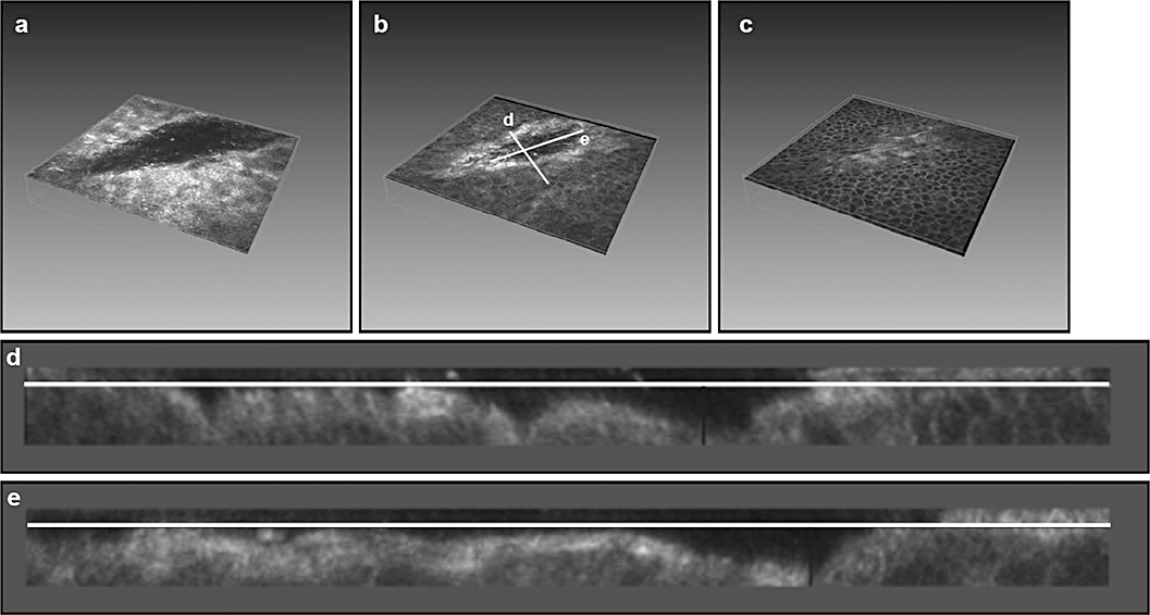
In vivo three-dimensional reconstruction of the ocular surface in corneal erosion. (a–c) In vivo confocal images of corneal erosion at the level of the superficial (a), upper (b) and lower wing cells (c): transverse and longitudinal axes (corresponding to Fig. 5d,e) are shown. (d,e) Reconstructed images of the transverse (d) and longitudinal (e) axes of the corneal erosion.
In order to overcome applanation artefacts the authors designed a novel contact cap for use with the HRT-II + RCM device.94 This innovative design minimizes applanation pressure on the area investigated, thus reducing artefacts that could potentially interfere with the confocal images, and improves the capability of correctly imaging the most superficial cell layer.
Non-ophthalmological application
Clinical application of CLSM outside ophthalmology is mainly limited by light interaction with human tissue. Confocal reflectance images with subcellular resolution can be obtained at depths up to 500 µm within the human tissue.95 This is adequate to image the entire epithelium in most tissues. The penetration depth is limited by the signal-to-noise ratio and the background, because of parasitic out-of-focus scattering (Fig. 10).
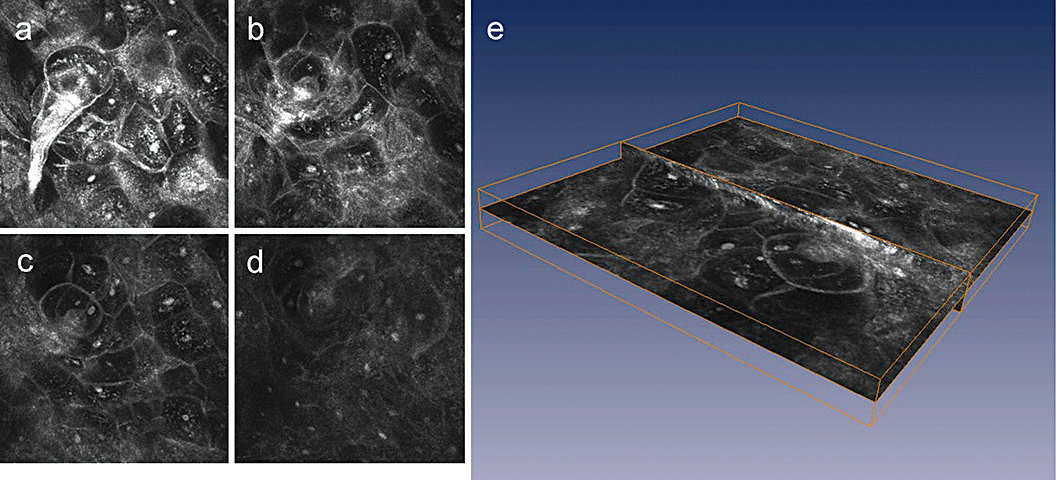
Mucous membrane in different depths (a–d) and three-dimensional reconstruction, z-scan = 50 µm.
A number of studies have been carried out to assess the ability to image the characteristics of special tissue properties. To date, CSLM has been used to picture subcellular features and the pathological alterations of the oral cavity, cervix and esophagus.96–98 Confocal imaging of human skin can provide detailed images of cell morphology and tissue architecture of the entire epithelium.99,100 A number of pathological skin conditions have been investigated.101–104 CLSM has also been performed in the amelanotic epithelial tissue of the gastrointestinal tract,105 cervix,99 lip and tongue,106,107 and can provide detailed images of the cell morphology and tissue architecture of the oropharynx.108
Future developments
In vivo CM provides a universal tool to assess corneal architecture and morphology with properties similar to that provided by conventional histopathology, without the invasive preparation and need for biopsy. Outside ophthalmology, this emerging technology has the potential to improve the specificity of detection methods for early neoplastic lesions, the assessment of tumour margins and the detection of response to chemotherapy.95 Current systems have some limitations, but the use of new technologies, for example multi-photon imaging or second harmonic imaging,109,110 all offer new possibilities.
By highly focusing the laser light, several imaging techniques can be used. On the one hand, confocal laser microscopy allows the imaging of tissues without prior staining or treatment of the samples that are being examined. On the other hand, non-linear interaction mechanisms, such as multi-photon absorption or frequency conversion, can be produced by using a highly focused pulsed laser. By using ultrashort laser pulses with pulse durations of some hundreds of femtoseconds, the used power stays within milliwatt range. In this way, induced autofluorescence or fluorescence of introduced pigments can be used to produce images of submicrometer range. Both technologies, the conventional confocal tissue microscopy and the non-linear imaging procedures such as multiphoton microscopy, are being used intensively to determine different tissue structures in a non-invasive manner. So far, despite the help of pathologists and cell biologists, there are still unanswered questions about which cell elements or molecules are having an effect on the images (Fig. 11). Not until there is a more comprehensive understanding and interpretation of the new images will the new technology be used to full effect.
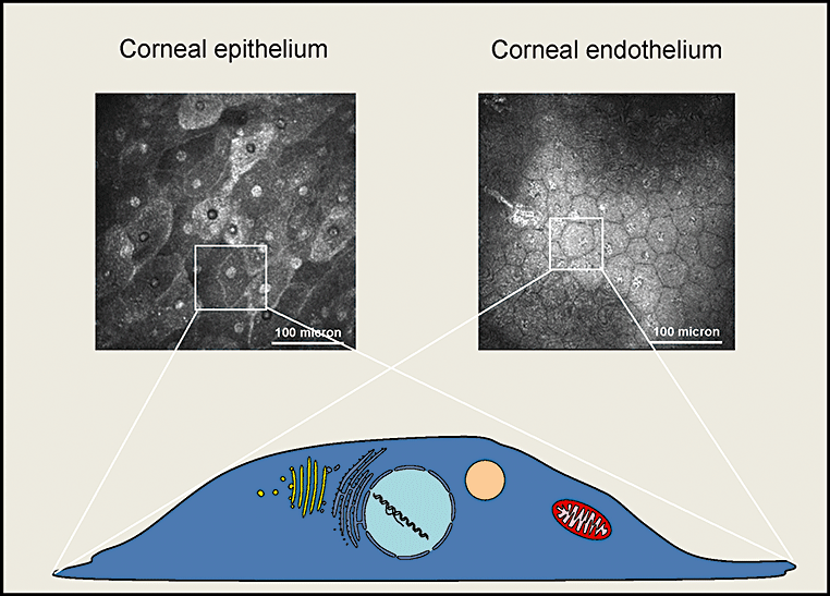
Different cell populations can be identified (epithelium and endothelium), but basic information about the scattering structures which are responsible for image formation is missing.
Conlusions
There is no doubt that the use and combination of techniques, such as laser scanning, fast digital signal capture/processing and image stabilization, are pushing forward the frontiers of in vivo CM. These new technologies are constantly improving because of the engineering skill and dedication of physicists and engineers, who carefully listen to the wishes and dreams of clinicians.
Acknowledgement
The work was supported in part by the DFG (Transregio 37, Micro- und Nanosystems in Medicine – Reconstruction of Biological Functions) and by an internal grant from the University of Rostock (FORUN N 889009).


